Gps Tracker Schematic Diagram . it’s easy to share your location using your phone. A microcontroller, a gps unit,. a gps tracker circuit diagram is a schematic representation of the electronic components and their connections that are used to build a gps tracker. In this article, carlo designs and builds a device with a gps module, capable of notifying your position to an android app in real time and sending gps data via sms. gps tracking circuits allow for precise tracking of an object's movement or location because they use a combination of. a gps tracker wiring diagram provides a visual representation of how the different components of a gps tracker are connected. on a basic level, a gps tracker circuit diagram is composed of several different parts: a gps compass tracker schematic is a diagram used to show how the components of a gps device are arranged.
from medium.com
gps tracking circuits allow for precise tracking of an object's movement or location because they use a combination of. A microcontroller, a gps unit,. a gps compass tracker schematic is a diagram used to show how the components of a gps device are arranged. In this article, carlo designs and builds a device with a gps module, capable of notifying your position to an android app in real time and sending gps data via sms. a gps tracker circuit diagram is a schematic representation of the electronic components and their connections that are used to build a gps tracker. on a basic level, a gps tracker circuit diagram is composed of several different parts: it’s easy to share your location using your phone. a gps tracker wiring diagram provides a visual representation of how the different components of a gps tracker are connected.
Creating a GPS tracking device using an Arduino. by Manind Gera Medium
Gps Tracker Schematic Diagram on a basic level, a gps tracker circuit diagram is composed of several different parts: a gps tracker circuit diagram is a schematic representation of the electronic components and their connections that are used to build a gps tracker. In this article, carlo designs and builds a device with a gps module, capable of notifying your position to an android app in real time and sending gps data via sms. a gps tracker wiring diagram provides a visual representation of how the different components of a gps tracker are connected. it’s easy to share your location using your phone. a gps compass tracker schematic is a diagram used to show how the components of a gps device are arranged. on a basic level, a gps tracker circuit diagram is composed of several different parts: A microcontroller, a gps unit,. gps tracking circuits allow for precise tracking of an object's movement or location because they use a combination of.
From schematicfixtelsons.z22.web.core.windows.net
Circuit Diagram Of Gps Tracking Device Gps Tracker Schematic Diagram a gps tracker wiring diagram provides a visual representation of how the different components of a gps tracker are connected. a gps compass tracker schematic is a diagram used to show how the components of a gps device are arranged. it’s easy to share your location using your phone. gps tracking circuits allow for precise tracking. Gps Tracker Schematic Diagram.
From schematicenginebarry.z19.web.core.windows.net
Gps Gsm Tracker Circuit Diagram Gps Tracker Schematic Diagram a gps tracker circuit diagram is a schematic representation of the electronic components and their connections that are used to build a gps tracker. In this article, carlo designs and builds a device with a gps module, capable of notifying your position to an android app in real time and sending gps data via sms. a gps compass. Gps Tracker Schematic Diagram.
From circuitdigest.com
Vehicle Tracking System Project using GPS and Arduino Gps Tracker Schematic Diagram In this article, carlo designs and builds a device with a gps module, capable of notifying your position to an android app in real time and sending gps data via sms. it’s easy to share your location using your phone. a gps tracker wiring diagram provides a visual representation of how the different components of a gps tracker. Gps Tracker Schematic Diagram.
From circuitdigest.com
Build Low Power SMS Based Vehicle Tracking System with A9G GSM+GPS Gps Tracker Schematic Diagram a gps tracker wiring diagram provides a visual representation of how the different components of a gps tracker are connected. a gps compass tracker schematic is a diagram used to show how the components of a gps device are arranged. on a basic level, a gps tracker circuit diagram is composed of several different parts: In this. Gps Tracker Schematic Diagram.
From manuallisthighjacks.z21.web.core.windows.net
Gps Tracking Circuit Diagrams Gps Tracker Schematic Diagram it’s easy to share your location using your phone. a gps tracker circuit diagram is a schematic representation of the electronic components and their connections that are used to build a gps tracker. A microcontroller, a gps unit,. a gps compass tracker schematic is a diagram used to show how the components of a gps device are. Gps Tracker Schematic Diagram.
From circuitdigest.com
Lora Based GPS Tracker using Arduino and LoRa Shield Gps Tracker Schematic Diagram it’s easy to share your location using your phone. a gps tracker wiring diagram provides a visual representation of how the different components of a gps tracker are connected. a gps tracker circuit diagram is a schematic representation of the electronic components and their connections that are used to build a gps tracker. gps tracking circuits. Gps Tracker Schematic Diagram.
From how2electronics.com
GPS+GSM Based Vehicle Tracking System using Arduino Gps Tracker Schematic Diagram it’s easy to share your location using your phone. gps tracking circuits allow for precise tracking of an object's movement or location because they use a combination of. on a basic level, a gps tracker circuit diagram is composed of several different parts: a gps tracker wiring diagram provides a visual representation of how the different. Gps Tracker Schematic Diagram.
From wiring.hpricorpcom.com
calamp gps wiring diagram Wiring Diagram and Schematic Gps Tracker Schematic Diagram gps tracking circuits allow for precise tracking of an object's movement or location because they use a combination of. a gps tracker circuit diagram is a schematic representation of the electronic components and their connections that are used to build a gps tracker. a gps compass tracker schematic is a diagram used to show how the components. Gps Tracker Schematic Diagram.
From medium.com
Creating a GPS tracking device using an Arduino. by Manind Gera Medium Gps Tracker Schematic Diagram A microcontroller, a gps unit,. a gps tracker wiring diagram provides a visual representation of how the different components of a gps tracker are connected. it’s easy to share your location using your phone. a gps tracker circuit diagram is a schematic representation of the electronic components and their connections that are used to build a gps. Gps Tracker Schematic Diagram.
From oshwlab.com
GPSTrackerSTM32Neo7N EasyEDA open source hardware lab Gps Tracker Schematic Diagram a gps compass tracker schematic is a diagram used to show how the components of a gps device are arranged. on a basic level, a gps tracker circuit diagram is composed of several different parts: gps tracking circuits allow for precise tracking of an object's movement or location because they use a combination of. a gps. Gps Tracker Schematic Diagram.
From circuitcellar.com
Build a MultiPurpose GPS Tracker Circuit Cellar Gps Tracker Schematic Diagram a gps tracker circuit diagram is a schematic representation of the electronic components and their connections that are used to build a gps tracker. on a basic level, a gps tracker circuit diagram is composed of several different parts: In this article, carlo designs and builds a device with a gps module, capable of notifying your position to. Gps Tracker Schematic Diagram.
From makersportal.com
Portable GPS Tracker with Arduino — Maker Portal Gps Tracker Schematic Diagram gps tracking circuits allow for precise tracking of an object's movement or location because they use a combination of. it’s easy to share your location using your phone. a gps compass tracker schematic is a diagram used to show how the components of a gps device are arranged. a gps tracker circuit diagram is a schematic. Gps Tracker Schematic Diagram.
From www.circuits-diy.com
Tracking Transmitter Circuit Diagram Gps Tracker Schematic Diagram In this article, carlo designs and builds a device with a gps module, capable of notifying your position to an android app in real time and sending gps data via sms. on a basic level, a gps tracker circuit diagram is composed of several different parts: gps tracking circuits allow for precise tracking of an object's movement or. Gps Tracker Schematic Diagram.
From www.pinterest.co.uk
Vehicle Tracking and Accident Alert System using MSP430 Launchpad and Gps Tracker Schematic Diagram a gps tracker circuit diagram is a schematic representation of the electronic components and their connections that are used to build a gps tracker. gps tracking circuits allow for precise tracking of an object's movement or location because they use a combination of. on a basic level, a gps tracker circuit diagram is composed of several different. Gps Tracker Schematic Diagram.
From schematicpartfix.z21.web.core.windows.net
Gps Car Tracker Circuit Diagram Gps Tracker Schematic Diagram a gps tracker circuit diagram is a schematic representation of the electronic components and their connections that are used to build a gps tracker. In this article, carlo designs and builds a device with a gps module, capable of notifying your position to an android app in real time and sending gps data via sms. A microcontroller, a gps. Gps Tracker Schematic Diagram.
From projectsfactory.in
Gsm Gps Based Wildlife Animal Tracking System Gps Tracker Schematic Diagram a gps tracker circuit diagram is a schematic representation of the electronic components and their connections that are used to build a gps tracker. a gps compass tracker schematic is a diagram used to show how the components of a gps device are arranged. on a basic level, a gps tracker circuit diagram is composed of several. Gps Tracker Schematic Diagram.
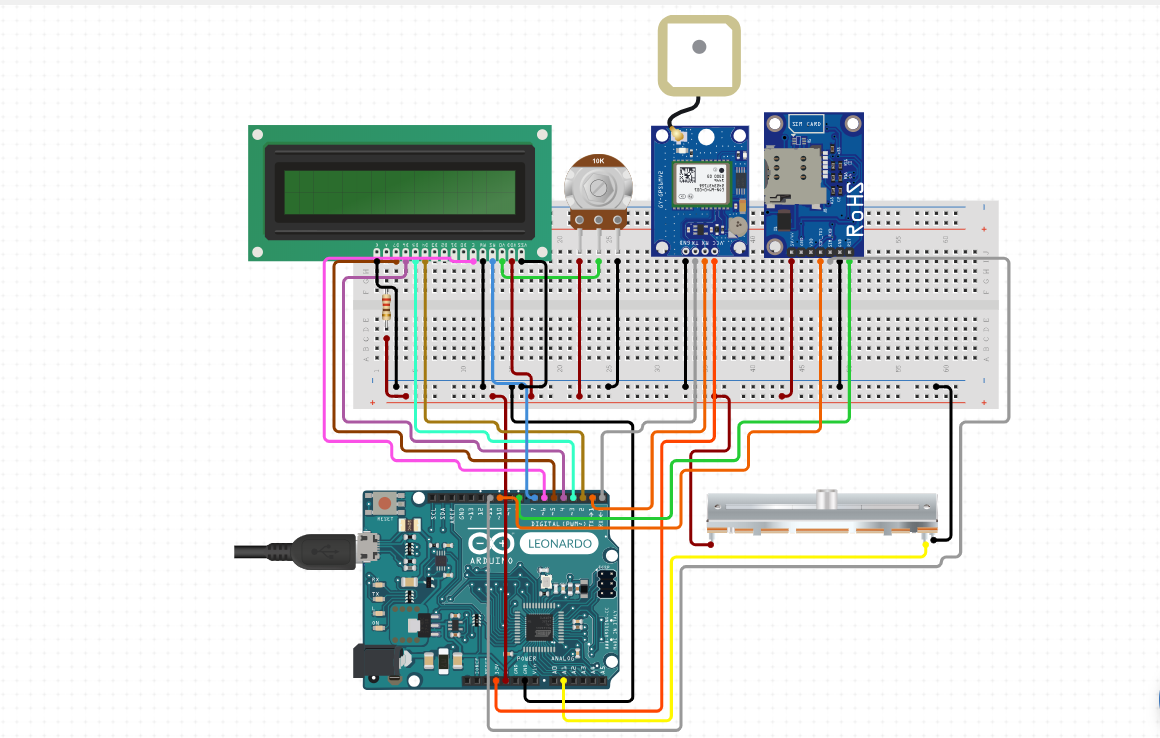
From electronicsprojects.in
Location Tracker using Arduino, NEO 6M GPS Module and SIM900A GSM Gps Tracker Schematic Diagram In this article, carlo designs and builds a device with a gps module, capable of notifying your position to an android app in real time and sending gps data via sms. A microcontroller, a gps unit,. a gps compass tracker schematic is a diagram used to show how the components of a gps device are arranged. a gps. Gps Tracker Schematic Diagram.
From schematicrepurify.z21.web.core.windows.net
Gps Tracker Circuit Diagram Datasheet Gps Tracker Schematic Diagram gps tracking circuits allow for precise tracking of an object's movement or location because they use a combination of. A microcontroller, a gps unit,. a gps tracker circuit diagram is a schematic representation of the electronic components and their connections that are used to build a gps tracker. In this article, carlo designs and builds a device with. Gps Tracker Schematic Diagram.